- 您现在的位置:买卖IC网 > Sheet目录198 > 8924G (Aavid Thermalloy)CARD GUIDE EJECTOR PULLER
�� �
�
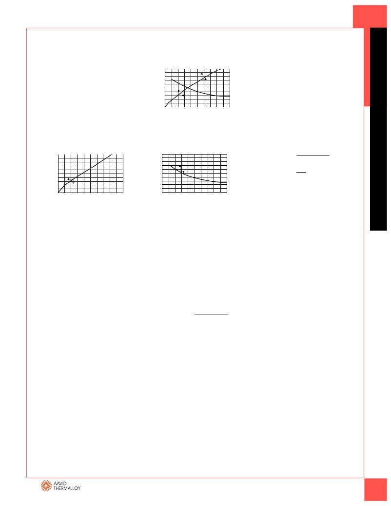
�Reading� a� Thermal� Performance� Graph�
�The� performance� graphs� you� will� see� in� this�
�catalog� (see� graph� 579802)� are� actually� a�
�579802�
�Air� Velocity—Feet� Per� Minute�
�CONVERTING� VOLUME�
�TO� VELOCITY�
�composite� of� two� separate� graphs� which�
�have� been� combined� to� save� space.� The� small�
�arrows� on� each� curve� indicate� to� which� axis�
�the� curve� corresponds.� Thermal� graphs� are�
�published� assuming� the� device� to� be� cooled�
�is� properly� mounted� and� the� heat� sink� is� in�
�100�
�80�
�60�
�40�
�20�
�0�
�0�
�200�
�400�
�600� 800�
�1000�
�20�
�16�
�12�
�8�
�4�
�0�
�Although� most� fans� are� normally� rated� and�
�compared� at� their� free� air� delivery� at� zero�
�back� pressure,� this� is� rarely� the� case� in� most�
�applications.� For� accuracy,� the� volume� of�
�output� must� be� derated� 60%–80%� for�
�the� anticipation� of� back� pressure.�
�its� recommended� mounting� position.�
�0�
�1�
�2� 3� 4�
�5�
�Heat� Dissipated—Watts�
�EXAMPLE:� The� output� air� volume�
�of� a� fan� is� given� as� 80� CFM.� The� output� area�
�GRAPH� A�
�GRAPH� B�
�Air� Velocity—Feet� Per� Minute�
�is� 6� inches� by� 6� inches� or� 36� in� 2� or� 25� ft� 2� .�
�To� find� velocity:�
�100�
�80�
�0�
�200�
�400�
�600� 800�
�1000�
�20�
�16�
�Velocity� (LFM)� =�
�Volume� (CFM)�
�area� (ft� 2� )�
�Velocity� =� =� 320�
�60�
�40�
�20�
�12�
�8�
�4�
�80�
�0.25�
�Velocity� is� 320� LFM,� which� at� 80%,�
�0�
�0�
�1�
�2� 3�
�4�
�5�
�0�
�derates� to� 256� LFM.�
�Heat� Dissipated—Watts�
�GRAPH� A� is� used� to� show� heat� sink� perform-�
�ance� when� used� in� a� natural� convection� envi-�
�ronment� (i.e.� without� forced� air).� This� graph�
�starts� in� the� lower� left� hand� corner� with� the�
�horizontal� axis� representing� the� heat� dissipa-�
�tion� (watts)� and� the� vertical� left� hand� axis�
�representing� the� rise� in� heat� sink� mounting�
�surface� temperature� above� ambient� (°C).� By�
�knowing� the� power� to� be� dissipated,� the�
�temperature� rise� of� the� mounting� surface�
�can� be� predicted.� Thermal� resistance� in� natu-�
�ral� convection� is� determined� by� dividing� this�
�temperature� rise� by� the� power� input� (°C/W).�
�EXAMPLE� A:� Aavid� Thermalloy� part� number�
�579802� is� to� be� used� to� dissipate� 3� watts� of�
�power� in� natural� convection.� Because� we� are�
�dealing� with� natural� convection,� we� refer� to�
�graph� “A”.� Knowing� that� 3� watts� are� to� be� dis-�
�sipated,� follow� the� grid� line� to� the� curve� and�
�find� that� at� 3� watts� there� is� a� temperature�
�rise� of� 75°C.� To� get� the� thermal� resistance,�
�divide� the� temperature� rise� by� the� power�
�dissipated,� which� yields� 25°C/W.�
�*� Linear� feet� per� minute�
�**� Cubic� feet� per� minute�
�GRAPH� B� is� used� to� show� heat� sink� per-�
�formance� when� used� in� a� forced� convec-�
�tion� environment� (i.e.� with� forced� air� flow�
�through� the� heat� sink).� This� graph� has� its�
�origin� in� the� top� right� hand� corner� with�
�the� horizontal� axis� representing� air� velocity�
�over� the� heat� sink� LFM*� and� the� vertical�
�axis� representing� the� thermal� resistance� of�
�the� heat� sink� (°C/W).� Air� velocity� is� calculat-�
�ed� by� dividing� the� output� volumetric� flow�
�rate� of� the� fan� by� the� cross-sectional� area�
�of� the� outflow� air� passage.�
�Velocity� (LFM)*� =� Volume� (CFM)**�
�area� (ft� 2� )�
�EXAMPLE� B:� For� the� same� application�
�we� add� a� fan� which� blows� air� over� the� heat�
�sink� at� a� velocity� of� 400� LFM.�
�The� addition� of� a� fan� indicates� the� use� of�
�forced� convection� and� therefore� we� refer�
�to� graph� “B”.� This� resistance� of� 9.50°C/W� is�
�then� multiplied� by� the� power� to� be� dissi-�
�pated,� 3� watts.� This� yields� a� temperature�
�rise� of� 28.5°C.�
�DESIGN� ASSISTANCE�
�Aavid� Thermalloy� can� assist� in� the� design�
�of� heat� sinks� for� both� forced� and� natural�
�convection� applications.� Contact� us� for� help�
�with� your� next� thermal� challenge.� For� more�
�information,� visit� our� web� site� at:�
�www.aavidthermalloy.com�
�AMERICA�
�USA� Tel:� +1� (603)� 224-9988� email:� info@aavid.com�
�ASIA�
�Singapore� Tel:� +65� 6362� 8388� email:� sales@aavid.com.sg�
�www.aavidthermalloy.com�
�EUROPE�
�Italy� Tel:� +39� 051� 764011� email:� sales.it@aavid.com�
�United� Kingdom� Tel:� +44� 1793� 401400� email:� sales.uk@aavid.com�
�Taiwan� Tel:� +886(2)� 2698-9888� email:� sales@aavid.com.tw�
�11�
�发布紧急采购,3分钟左右您将得到回复。
相关PDF资料
8AC2AK-65-249
JOYSTICK 8000 SINGLE W/BUTTON
8AS190-V3L
SWITCH FORMED LVR SPST 1A QC
8AS245-V3
SWITCH ROLLER SPDT 15A SCREW
8AS252-BZ
SWITCH PLUNGER SPDT QC
8AS254-BZ
SWITCH PLUNGER SPDT SCREW
8AS262-BZ
SWITCH WHEEL PLUNGER SPDT SCREW
8AS264-MT
SWITCH PLUNGER SPDT QC
8LS1-L
SWITCH 1NC 1NO DPDT SNAP ACTION
相关代理商/技术参数
8925
功能描述:LED 安装硬件 LED SPACER .650 RoHS:否 制造商:Bivar 产品:LED Mounting Clips LED 大小:5 mm 材料:Nylon 颜色:Black 主体长度:4.4 mm 面板厚度尺寸: 封装:Bulk
8925.2
功能描述:安全继电器 RMB2U8, 8ch Relay Module110VAC, DPDT, Bussed, N RoHS:否 制造商:Phoenix Contact 触点形式: 线圈电压:24 VDC 触点额定值:230 mA 端接类型:Spring Cage
8925.3
功能描述:安全继电器 RMB2X8, 8ch Relay Module220VAC, DPDT, Bussed, N RoHS:否 制造商:Phoenix Contact 触点形式: 线圈电压:24 VDC 触点额定值:230 mA 端接类型:Spring Cage
892513-000
制造商:TE Connectivity 功能描述:HEAT SHRNK TBING POLYFN BLU SPL - Cable Rools/Shrink Tubing 制造商:TE Connectivity 功能描述:HEAT SHRINK TUBING 制造商:TE Connectivity 功能描述:Heat Shrink Tubing ST Polyolefin Blue Thin Spool 制造商:TE Connectivity 功能描述:MT2000-2.0-6-SP
892531-000
制造商:TE Connectivity 功能描述:55 CABLE - Cable Rools/Shrink Tubing 制造商:TE Connectivity 功能描述:55PC2211-18-9-92CS2502
89254-02
功能描述:键锁开关 FLASH/KEY SWITCHES RoHS:否 制造商:C&K Components 触点形式:1 Form A (SPST-NO) 开关功能:Momentary 触点额定值: 电流额定值:100 mA 电压额定值 AC:250 VAC 端接类型:Through Hole 键类型:Keyswitch 变址: 位置数量:1 外壳材料:
89256
制造商:Brady Corporation 功能描述:Cap 0.0056uF 50VDC YSP 10% 9.5 X 4mm RDL 5.1mm 制造商:NTE Electronics 功能描述:Cap Ceramic 0.0056uF 50V YSP 10% (9.5 X 4mm) Radial 5.1mm 85°C
89256-0000
功能描述:I/O 连接器 I/O HOUS 4P F ASSY RoHS:否 制造商:Hirose Connector 产品:Plugs 系列:DH 端口数量: 位置/触点数量:51 节距:1 mm 触点电镀: 触点材料: 型式:Male 电流额定值:0.5 A 安装风格:Cable 端接类型:IDC 颜色: 安装角: